Authoritative ANSI B16.5 / ASME B16.47 Weld Neck Flanges Manufacturers in India.
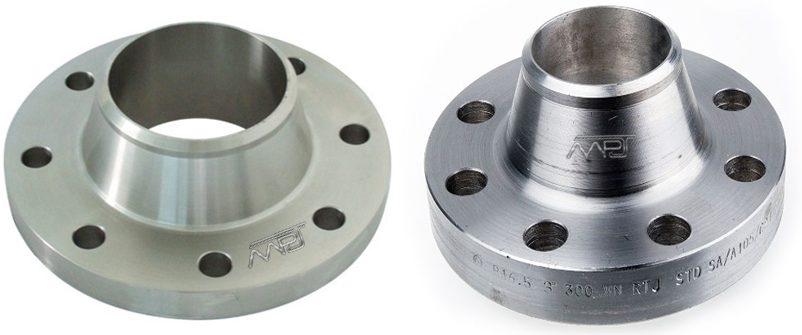
As one of the leaders amongst Manufacturers, Stockist, and Exporters of Raised Face Weld Neck Flange, ASME B16.5 / ANSI B16.47 Welding Neck Flange, We are offering competitive prices in India on DIN Weld Neck Flange, Series A & B WNRF Flanges, MSS Weld Neck Flange.
We keep adequate stock of SS Weld Neck Flanges, Alloy Steel Weld Neck Flanges, Nickel Alloy 200 WN Flange, Carbon Steel Weld Neck Flange, Inconel Weld Neck Flange, Hastelloy Weld Neck Flange, Copper Nickel WNRF Flanges, Duplex & Super Duplex Weld Neck Flange, Alloy 20 Weld Neck Flange in all Dimensions to satisfy any small and large quantity orders from our valuable customers.
- What is a Welding Neck Flange
- Welding Neck Flange Specifications
- Welding Neck Flange Materials and Grades
- Why Choose us to Buy Welding Neck Flange
- Welding Neck Flange Price in India
- Welding Neck Flange Dimensions
- Welding Neck Flange Dimensional Tolerances
- Welding Neck Flange Manufacturing Process
- Welding Neck Flange Application Industries
- Cities We Export Welding Neck Flange
- Countries We Export Welding Neck Flange
What is a Weld Neck Flanges
A weld neck flanges (also known as a high-hub flange and tapered hub flange) is a type of flange. There are two designs. The regular type is used with pipes. The long type is unsuitable for pipes and is used in process plant.
A weld neck flange consists of a circular fitting with a protruding rim around the circumference. Generally machined from a forging, these flanges are typically butt welded to a pipe. The rim has a series of drilled holes that permit the flange to be affixed to another flange with bolts.
Weld Neck Flanges Specifications
| Type | : | WN Forged Flange |
| Size | : | ½” (15 NB) to 48″ (1200NB) |
| Standard | : | ANSI B16.5, ANSI B16.47, ANSI B16.36, ANSI B16.48, BS 4504, EN1092, UNI 2277/2278, DIN, JIS, SABS1123, GOST-12820 |
| Class | : | 150 LBS, 300 LBS, 600 LBS, 900 LBS, 1500 LBS, 2500 LBS, DIN Standard ND-6,10, 16, 25, 40 Etc. |
| DIN | : | DIN2527, DIN2566, DIN2573, DIN2576, DIN2641, DIN2642, DIN2655, DIN2656, DIN2627, DIN2628, DIN2629, DIN 2631, DIN2632, DIN2633, DIN2634, DIN2635, DIN2636,DIN2637, DIN2638, DIN2673 |
| BS | : | BS4504 , BS4504, BS1560, BS10 |
| In Form | : | SORF, WNRF, BLRF, SWRF, LAP Joint, Threaded, Reducing, Spectacle, etc |
| Specialize | : | As per drawing |
| Coating/Surface Treatment | : | Anti-rust Paint, Oil Black Paint, Yellow Transparent, Zinc Plated, Cold and Hot Dip Galvanized |
| Connection Type | : | Ring Type Joint, Lap-Joint Face, Raised Face, Flat Face, Large Male-Female, Small Male-Female, Large |
| Tongue & Groove, Small Tongue & Groove | ||
| Flange Face Type | : | Flat Face (FF), Raise Face (RF), Ring Joint (RJT) |
| Dimensions | : | ANSI B16.5, ANSI B16.47 Series A & B, MSS SP44, ASA, API-605, AWWA, Custom Drawings |
| Packing | : | No Fumigate or Fumigate Plywood/Wood Pallet or Case |
| Usage | : | Oil Field, Offshore, Water System, Shipbuilding, Natural Gas, Electric Power, Pipe Projects etc. |
Weld Neck Flanges Materials & Grades
| Materials | : | Standard, Grades |
| Stainless Steel Weld Neck Flanges | : | ASTM A 182, A 240 F 304, 304L, 304H, 316, 316L, 316Ti, 310, 310S, 321, 321H, 317, 347, 347H,904L |
| Carbon Steel Weld Neck Flanges | : | ASTM / ASME A/SA 105 ASTM / ASME A 350 , ASTM A 181 LF 2 / A516 Gr.70 A36, A694 F42, F46, F52, |
| F60, F65, F70 | ||
| Alloy Steel Weld Neck Flanges | : | ASTM / ASME A/SA 182 & A 387 F1, F5, F9, F11, F12, F22, F91 |
| Duplex Steel Weld Neck Flanges | : | ASTM / ASME A/SA 182 F 44, F 45, F51, F 53, F 55, F 60, F 61 |
| 6% Moly / Super Duplex Weld Neck Flanges | : | ASTM / ASME A/SA 182 F 44, F 45, F51, F 53, F 55, F 60, F 61 |
| Low Temperature Steel Weld Neck Flanges | : | ASTM A350 LF2, LF3, LF6 |
| High Yield Weld Neck Flanges | : | ASTM A694 F42, F52, F60, F65, F70 |
| Nickel Alloys Weld Neck Flanges | : | ASTM SB564, SB160, SB472, SB162 – Nickel 200 (UNS No. N02200), Nickel 201 (UNS No. N02201), Monel 400 (UNS No. N04400), Monel 500 (UNS No. N05500), Inconel 800 (UNS No. N08800), Inconel 825 (UNS No. N08825), Inconel 600 (UNS No. N06600), Inconel 625 (UNS No. N06625), Inconel 601 (UNS No. N06601), Hastelloy C 276 (UNS No. N10276), Alloy 20 (UNS No. N08020) |
| Copper Alloys Weld Neck Flanges | : | ASTM SB 61 , SB62 , SB151 , SB152 – UNS No. C 70600 (Cu-Ni 90/10), C 71500 (Cu-Ni 70/30), UNS No. C 10100, 10200, 10300, 10800, 12000, 12200 |
| Alloys Weld Neck Flanges | : | ALLOY 20, ALLOY C, ALLOY C276, ALLOY B2 |
| Other Grade of Weld Neck Flanges | : | Bronze, Brass, Cupro Nickel, Titanium, Inconel, Monel, Hastelloy |
Why Choose M P Jain Tubing Solutions LLP
- » M P Jain Tubing Solutions LLP welcome small and large quantity orders and are capable of manufacture Weld Neck Flanges according to drawings provided by customers.
- » An ISO / OHSAS / PED Certified Stockist and Exporters of WNRF Flanges Manufactured with the finest quality raw materials (Stainless Steel, Duplex, Super Duplex, Nickel Alloys, Cupro Nickel, Alloy 20, Carbon Steel, etc.) results in High-Quality End Products.
- » With the quality, we also guarantee On-Time Delivery of ASME B16.5/B16.47 WN Flanges. If clients have any query regarding purchased products they can chat with our support team live on a website (24/7 support service) or they can mail us on exports@mpjainco.com.
- » Our state-of-the-art infrastructure is located in the industrial hub, Mumbai India and we possess a team of highly qualified as well as experienced professionals. We continuously keep on upgrading our machinery to meet the challenges of fiercely competitive and ever changing market demands.
- » We believe that along with Competitive Prices, the Quality performance of products and customer satisfaction are the basis for growth and success of our business. We tend to present innovative solutions and services to our customers.
- » Since 1972 we are in this business and Manufacturing Welding Neck Flanges in different standards like ANSI, ASME, BS, DIN, API. Product Supplied by us are accepted by Client’s in various industries small basic industries such as Textile, Paper, Engineering, Sugar, Dairy, Cement to more complex such as Petrochemical, Oil & Gas, Power, Onshore & Offshore ETC. Our main export market is Bahrain, Bangladesh, Iraq, Japan, Jordan, Kazakhstan, Lebanon, Myanmar, Oman, Philippines, Qatar, Saudi Arabia, Sri Lanka, Thailand, Turkey, UAE, Uzbekistan etc.
Weld Neck Flanges Price List
Following is Weld Neck (WNRF) Flanges price in India. This price range also depends on minimum order and might vary without any prior information. For more details contact us now and get Instant Quote.

Reference:alibaba
ASME B16.5 Weld Neck Flanges Dimensions:

| ANSI, ASME, ASA, B16.5 150lb/sq.in. WELDING NECK FLANGE RF | |||||||||||
|---|---|---|---|---|---|---|---|---|---|---|---|
| ø | D | b | g | m | a | J* | h | k | Holes | l | Kg. |
| 1/2″ | 88,9 | 11,1 | 34,9 | 30,2 | 21,3 | 15,7 | 47,6 | 60,3 | 4 | 15,9 | 0,500 |
| 3/4″ | 98,4 | 12,7 | 42,9 | 38,1 | 26,7 | 20,8 | 52,4 | 69,8 | 4 | 15,9 | 0,700 |
| 1″ | 107,9 | 14,3 | 50,8 | 49,2 | 33,5 | 26,7 | 55,6 | 79,4 | 4 | 15,9 | 1,100 |
| 1 1/4″ | 117,5 | 15,9 | 63,5 | 58,8 | 42,2 | 35,1 | 57,1 | 88,9 | 4 | 15,9 | 1,500 |
| 1 1/2″ | 127,0 | 17,5 | 73,0 | 65,1 | 48,3 | 40,9 | 61,9 | 98,4 | 4 | 15,9 | 1,800 |
| 2″ | 152,4 | 19,0 | 92,1 | 77,8 | 60,3 | 52,6 | 63,5 | 120,6 | 4 | 19,0 | 2,700 |
| 2 1/2″ | 177,8 | 22,2 | 104,8 | 90,5 | 73,1 | 62,7 | 69,8 | 139,7 | 4 | 19,0 | 4,400 |
| 3″ | 190,5 | 23,8 | 127,0 | 107,9 | 88,9 | 78,0 | 69,8 | 152,4 | 4 | 19,0 | 5,200 |
| 3 1/2″ | 215,9 | 23,8 | 139,7 | 122,2 | 101,6 | 90,2 | 71,4 | 177,8 | 8 | 19,0 | 6,400 |
| 4″ | 228,6 | 23,8 | 157,2 | 134,9 | 114,3 | 102,4 | 76,2 | 190,5 | 8 | 19,0 | 7,500 |
| 5″ | 254,0 | 23,8 | 185,7 | 163,5 | 141,2 | 128,3 | 88,9 | 215,9 | 8 | 22,2 | 9,200 |
| 6″ | 279,4 | 25,4 | 215,9 | 192,1 | 168,4 | 154,2 | 88,9 | 241,3 | 8 | 22,2 | 11,000 |
| 8″ | 342,9 | 28,6 | 269,9 | 246,1 | 219,1 | 202,7 | 101,6 | 298,4 | 8 | 22,2 | 18,300 |
| 10″ | 406,4 | 30,2 | 323,8 | 304,8 | 273,0 | 254,5 | 101,6 | 361,9 | 12 | 25,4 | 25,000 |
| 12″ | 482,6 | 31,7 | 381,0 | 365,1 | 323,8 | 304,8 | 114,3 | 431,8 | 12 | 25,4 | 39,000 |
| 14″ | 533,4 | 34,9 | 412,7 | 400,0 | 355,6 | 336,5 | 127,0 | 476,2 | 12 | 28,6 | 51,000 |
| 16″ | 596,9 | 36,5 | 469,9 | 457,2 | 406,4 | 387,3 | 127,0 | 539,7 | 16 | 28,6 | 60,000 |
| 18″ | 635,0 | 39,7 | 533,4 | 504,8 | 457,2 | 438,1 | 139,7 | 577,8 | 16 | 31,7 | 71,000 |
| 20″ | 698,5 | 42,9 | 584,2 | 558,8 | 508,0 | 488,9 | 144,5 | 635,0 | 20 | 31,7 | 88,000 |
| 22″ | 749,3 | 46,0 | 641,2 | 609,6 | 558,8 | 539,7 | 149,2 | 692,1 | 20 | 34,9 | 102,000 |
| 24″ | 812,8 | 47,6 | 692,1 | 663,6 | 609,6 | 590,5 | 152,4 | 749,3 | 20 | 34,9 | 119,000 |
| * | The data “J” corresponds to the STD schedule | ||||||||||
IMP. NOTES:
1. Class 150 flanges except Lap Joint will be furnished with 0.06 (1.6mm) raised face, which is included in ‘Thickness’ (C) and ‘Length through Hub’ (Y1), (Y3).
2. Blind Flanges may be made with the same hub as that used for Slip-on Flanges or without hub.
3. For Slip-on, Threaded, Socket Welding and Lap Joint Flanges, the hubs can be shaped either vertical from base to top or tapered within the limits of 7 degrees.
4. Depth of Socket (D) is covered by ANSI B 16.5 only in sizes through 3 inch, over 3 inch is at the manufacturer’s option.
5. The gasket surface and backside (bearing surface for bolting) are made parallel within 1 degree. To accomplish parallelism, spot facing is carried out according to MSS SP-9, without reducing thickness (C).
6. Welding Neck Flange Bore Size SCH10, SCH20, SCH30, STD, SCH40, SCH60, SCH80, SCH100, SCH 120, SCH140, SCH160, XS
| ANSI, ASME, ASA B16.5 300lb/sq.in. WELDING NECK FLANGE RF | |||||||||||
|---|---|---|---|---|---|---|---|---|---|---|---|
| ø | D | b | g | m | a | J* | h | k | Holes | l | Kg. |
| 1/2″ | 95,2 | 14,3 | 34,9 | 38,1 | 21,3 | 15,7 | 52,4 | 66,7 | 4 | 15,9 | 0,900 |
| 3/4″ | 117,5 | 15,9 | 42,9 | 47,6 | 26,7 | 20,8 | 57,1 | 82,5 | 4 | 19,0 | 1,500 |
| 1″ | 123,8 | 17,5 | 50,8 | 54,0 | 33,5 | 26,7 | 61,9 | 88,9 | 4 | 19,0 | 1,900 |
| 1 1/4″ | 133,3 | 19,0 | 63,5 | 63,5 | 42,2 | 35,1 | 65,1 | 98,4 | 4 | 19,0 | 2,600 |
| 1 1/2″ | 155,6 | 20,6 | 73,0 | 69,8 | 48,3 | 40,9 | 68,3 | 114,3 | 4 | 22,2 | 3,300 |
| 2″ | 165,1 | 22,2 | 92,1 | 84,1 | 60,3 | 52,6 | 69,8 | 127,0 | 8 | 19,0 | 3,600 |
| 2 1/2″ | 190,5 | 25,4 | 104,8 | 100,0 | 73,1 | 62,7 | 76,2 | 149,2 | 8 | 22,2 | 5,400 |
| 3″ | 209,5 | 28,6 | 127,0 | 117,5 | 88,9 | 78,0 | 79,4 | 168,3 | 8 | 22,2 | 7,400 |
| 3 1/2″ | 228,6 | 30,2 | 139,7 | 133,3 | 101,6 | 90,2 | 81,0 | 184,1 | 8 | 22,2 | 8,900 |
| 4″ | 254,0 | 31,7 | 157,2 | 146,0 | 114,3 | 102,4 | 85,7 | 200,0 | 8 | 22,2 | 11,900 |
| 5″ | 279,4 | 34,9 | 185,7 | 177,8 | 141,2 | 128,3 | 98,4 | 234,9 | 8 | 22,2 | 16,000 |
| 6″ | 317,5 | 36,5 | 215,9 | 206,4 | 168,4 | 154,2 | 98,4 | 269,9 | 12 | 22,2 | 20,200 |
| 8″ | 381,0 | 41,3 | 269,9 | 260,3 | 219,1 | 202,7 | 111,1 | 330,2 | 12 | 25,4 | 31,000 |
| 10″ | 444,5 | 47,6 | 323,4 | 320,7 | 273,0 | 254,5 | 117,5 | 387,3 | 16 | 28,6 | 44,300 |
| 12″ | 520,7 | 50,8 | 381,0 | 374,6 | 323,8 | 304,8 | 130,2 | 450,8 | 16 | 31,7 | 64,000 |
| 14″ | 584,2 | 54,0 | 412,7 | 425,4 | 355,6 | 336,5 | 142,9 | 514,3 | 20 | 31,7 | 88,000 |
| 16″ | 647,7 | 57,1 | 469,9 | 482,6 | 406,4 | 387,3 | 146,0 | 571,5 | 20 | 34,9 | 113,000 |
| 18″ | 711,2 | 60,3 | 533,4 | 533,4 | 457,2 | 438,1 | 158,7 | 628,6 | 24 | 34,9 | 134,000 |
| 20″ | 774,7 | 63,5 | 584,2 | 587,4 | 508,0 | 488,9 | 161,9 | 685,8 | 24 | 34,9 | 171,000 |
| 22″ | 838,2 | 66,7 | 641,2 | 641,2 | 558,8 | 539,7 | 165,1 | 742,9 | 24 | 41,3 | 195,000 |
| 24″ | 914,4 | 69,8 | 692,1 | 701,7 | 609,6 | 590,5 | 168,3 | 812,8 | 24 | 41,3 | 238,000 |
| * | The data “J” corresponds to the STD schedule | ||||||||||
IMP. NOTES:
1. Class 300 flanges except Lap Joint will be furnished with 0.06 (1.6mm) raised face, which is included in ‘Thickness’ (C) and ‘Length through Hub’ (Y1), (Y3).
2. Blind Flanges may be made with the same hub as that used for Slip-on Flanges or without hub.
3. For Slip-on, Threaded, Socket Welding and Lap Joint Flanges, the hubs can be shaped either vertical from base to top or tapered within the limits of 7 degrees.
4. Depth of Socket (D) is covered by ANSI B 16.5 only in sizes through 3 inch, over 3 inch is at the manufacturer’s option.
5. The gasket surface and backside (bearing surface for bolting) are made parallel within 1 degree. To accomplish parallelism, spot facing is carried out according to MSS SP-9, without reducing thickness (C).
6. Welding Neck Flange Bore Size SCH10, SCH20, SCH30, STD, SCH40, SCH60, SCH80, SCH100, SCH 120, SCH140, SCH160, XS
| ANSI/ASME/ASA B16.5 600lb/sq.in. WELDING NECK FLANGE RF | |||||||||||
|---|---|---|---|---|---|---|---|---|---|---|---|
| ø | D | b | g | m | a | J* | h | k | Holes | l | Kg. |
| 1/2″ | 95,2 | 14,3 | 34,9 | 38,1 | 21,3 | 15,7 | 52,4 | 66,7 | 4 | 15,9 | 0,900 |
| 3/4″ | 117,5 | 15,9 | 42,9 | 47,6 | 26,7 | 20,9 | 57,1 | 82,5 | 4 | 19,0 | 1,500 |
| 1″ | 123,8 | 17,5 | 50,8 | 54,0 | 33,5 | 26,7 | 61,9 | 88,9 | 4 | 19,0 | 1,900 |
| 1 1/4″ | 133,3 | 20,6 | 63,5 | 63,5 | 42,2 | 35,0 | 66,7 | 98,4 | 4 | 19,0 | 2,600 |
| 1 1/2″ | 155,6 | 22,2 | 73,0 | 69,8 | 48,3 | 40,9 | 69,8 | 114,3 | 4 | 22,2 | 3,300 |
| 2″ | 165,1 | 25,4 | 92,1 | 84,1 | 60,3 | 52,6 | 73,0 | 127,0 | 8 | 19,0 | 4,700 |
| 2 1/2″ | 190,5 | 28,6 | 104,8 | 100,0 | 73,1 | 62,7 | 79,4 | 149,2 | 8 | 22,2 | 6,500 |
| 3″ | 209,5 | 31,7 | 127,0 | 117,5 | 88,9 | 78,0 | 82,5 | 168,3 | 8 | 22,2 | 8,700 |
| 3 1/2″ | 228,6 | 34,9 | 139,7 | 133,3 | 101,6 | 90,1 | 85,7 | 184,1 | 8 | 25,4 | 11,200 |
| 4″ | 273,0 | 38,1 | 157,2 | 152,4 | 114,3 | 102,4 | 101,6 | 215,9 | 8 | 25,4 | 18,100 |
| 5″ | 330,2 | 44,4 | 185,7 | 188,9 | 141,2 | 128,2 | 114,3 | 266,7 | 8 | 28,6 | 30,500 |
| 6″ | 355,6 | 47,6 | 215,9 | 222,2 | 168,4 | 154,2 | 117,5 | 292,1 | 12 | 28,6 | 36,200 |
| 8″ | 419,1 | 55,6 | 269,9 | 273,0 | 219,1 | 202,7 | 133,3 | 349,2 | 12 | 31,7 | 56,500 |
| 10″ | 508,0 | 63,5 | 323,8 | 342,9 | 273,0 | 254,5 | 152,4 | 431,8 | 16 | 34,9 | 91,000 |
| 12″ | 558,8 | 66,7 | 381,0 | 400,0 | 323,8 | 304,8 | 155,6 | 488,9 | 20 | 34,9 | 105,000 |
| 14″ | 603,2 | 69,8 | 412,7 | 431,8 | 355,6 | * | 165,1 | 527,0 | 20 | 38,1 | 125,000 |
| 16″ | 685,8 | 76,2 | 469,9 | 495,3 | 406,4 | 177,8 | 603,2 | 20 | 41,3 | 178,000 | |
| 18″ | 742,9 | 82,5 | 533,4 | 546,1 | 457,2 | 184,1 | 654,0 | 20 | 44,4 | 261,000 | |
| 20″ | 812,8 | 88,9 | 584,2 | 609,6 | 508,0 | 190,5 | 723,9 | 24 | 44,4 | 268,000 | |
| 22″ | 869,9 | 95,2 | 641,2 | 666,7 | 558,8 | 196,8 | 777,9 | 24 | 47,6 | 328,000 | |
| 24″ | 939,8 | 101,6 | 692,1 | 717,5 | 609,6 | 203,2 | 838,2 | 24 | 50,8 | 380,000 | |
| * | The data “J” corresponds to the STD schedule | ||||||||||
| To be specifiedby customer | |||||||||||
IMP. NOTES:
1. Class 600 flanges except Lap Joint will be furnished with 0.25 (6.35mm) raised face, which is not included in ‘Thickness’ (C) and ‘Length through Hub’ (Y1), (Y3).
2. Blind Flanges may be made with the same hub as that used for Slip-on Flanges or without hub.
3. For Slip-on, Threaded, Socket Welding and Lap Joint Flanges, the hubs can be shaped either vertical from base to top or tapered within the limits of 7 degrees.
4. Dimensions of sizes 1/2 through 3 1/2 are the same as for Class 400 Flanges.
5. The gasket surface and backside (bearing surface for bolting) are made parallel within 1 degree. To accomplish parallelism, spot facing is carried out according to MSS SP-9, without reducing thickness (C).
6. Depth of Socket (D) is covered by ANSI B 16.5 only in sizes through 3 inch, over 3 inch is at the manufacturer’s option.
7. Welding Neck Flange Bore Size SCH10, SCH20, SCH30, STD, SCH40, SCH60, SCH80, SCH100, SCH 120, SCH140, SCH160, XS
ASME B16.5 Weld Neck Flanges Dimensional Tolerances
| Outside Diameter ≤ 24 = 1.6 mm | > 24 = ± 3.2 mm |
Inside Diameter ≤ 10 = ± 0.8 mm | 12 thru 18 = 1.6 mm | ≥ 20 = + 3.2 mm / – 1.6 mm |
| Diameter of Contact Face 1.6 mm Raised Face = ± 0.8 mm 6.35 mm Raised Face, Tongue & Groove / Male-Female = ± 0.4 mm |
Diameter of Hub at Base ≤ 24 = 1.6 mm | > 24 = ± 3.2 mm |
| Diameter of Hub at Point of Welding ≤ 5 = + 2.4 mm / – 0.8 mm | ≥ 6 = + 4.0 mm / – 0.8 mm |
Drilling Bolt Circle = 1.6 mm | Bolt Hole Spacing = ± 0.8 mm Eccentricity of Bolt Circle with Respect to Facing ≤ 2½ = 0.8 mm max. | ≥ 3 = 1.6 mm max |
| Thickness ≤ 18 = + 3.2 mm / – 0 | ≥ 20 = + 4.8 mm / – 0 |
Length thru Hub ≤ 10 = 1.6 mm | ≥ 12 = ± 3.2 mm |
Manufacturing Process of Weld Neck Flanges
We have Skilled staff to maintain the quality of products throughout the manufacturing process from selection of raw material to processing, marking, packaging, storage, and transportation. Our Welding Neck Flanges are 100% inspected before being packed and dispatched & all our materials are tested to International standards. Sometimes we also accept Third Party Inspection appointed by our clients.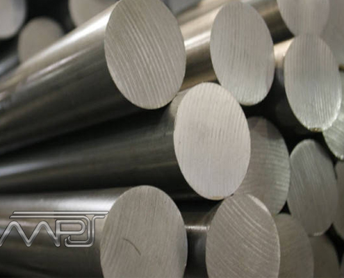
Raw Material
- » Raw Material Check
- » Quantity Check
- » Visual & Dimension Check
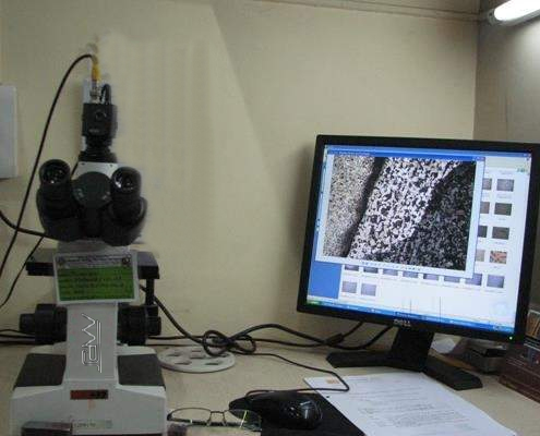
Material Inspection
- » Chemical Analysis Check
- » Preservation Analysis Certificate
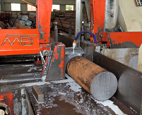
Material Cutting
- » Weight Measuring
- » Cut Surface Check
- » Marking
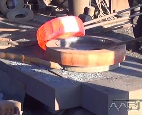
Flange Forging
- » Material Grade Check
- » Weight Measuring
- » Temperature Control
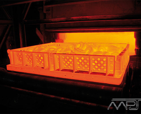
Heat Treatment
- » Normalizing
- » Tempering, Q.T
- » Solution Treatment
- » Mechanical Test
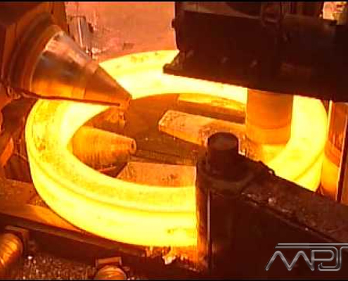
Forging Rolling
- » Material Grade Check
- » Weight Measuring
- » Temperature Check
- » Dimension Check
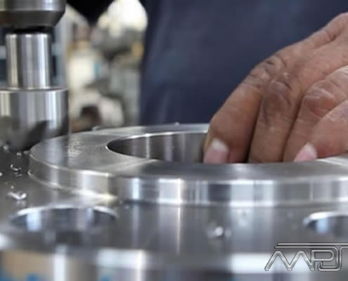
Final Inspection
- » Dimension size inspect
- » Visual Test
- » Nondestructive Test
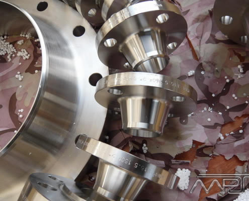
Rust Prevention
- » Preserve Check
- » Marking on the flange
- » Tectyl 506or Pickling or etc. Coating
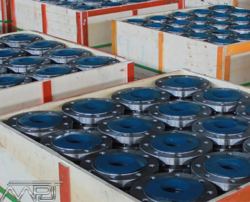
Well Packing
- » Packing Spec. Check
- » Packing Inspection
- » Delivery
Weld Neck Flanges Applications & Uses
Today M P Jain Tubing Solutions LLP is one of the leading manufacturer, stockists, and exporters of WN Flanges and supplying to various core industries like
Chemicals Fertilizers Industries
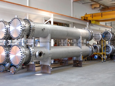
Heat Exchanger
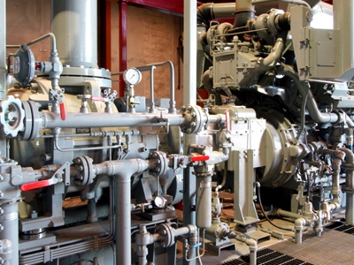
Instrumentation
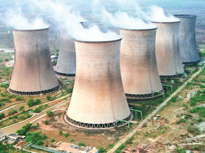
Nuclear Thermal Industries
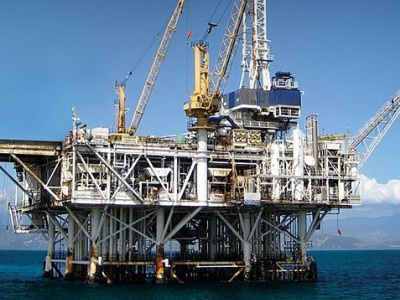
Oil Gas Industries
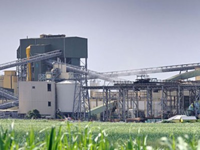
Pharmacy Surgical Industries

Refineries Petrochemicals

Water Gas Piping Systems
Cities We Export Weld Neck Flanges
|
|
|
|
Countries We Export Weld Neck Flanges
|
|
|
|


